Some photographs of the phasing interferometry radio telescope (146 MHz)
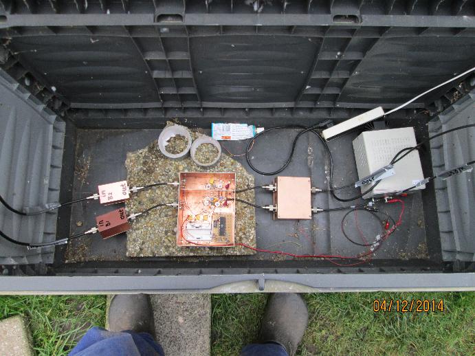
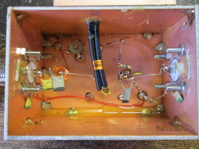
What you see inside the fieldbox ( and my feet)
From left to right: 2 times 10 dB 146 MHz amplifiers,
the 146 MHz to 31 MHz frequency convertors, the 2 times
19 db 31 MHz amplifer and the 13.6 Volt power supply
The 1 time 10 dB 146 MHz amplifier
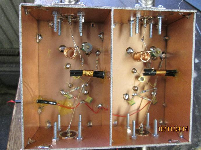
The 2 times 19 dB 31 MHz amplifier
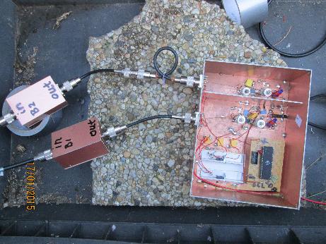
The 2 times 146 MHz to 31 MHz frequency convertors
(without shielding)
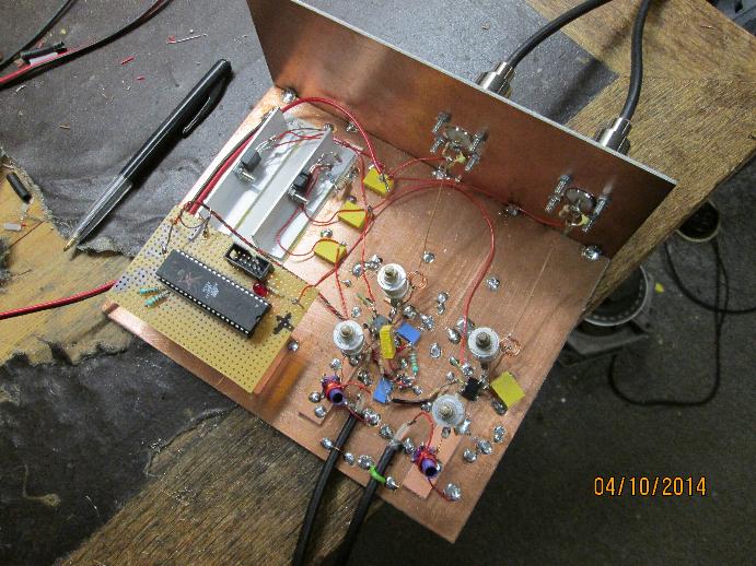
You see left the AVR microprocessor which programs
the si570 local oscillator, above it the 2 powerregulators
for the 5 volt for the microprocessor and the 3 Volt
for the si570.
At the right the 2 convertors.
top is 146 MHz input and at the lower part the 31 MHz output.
I build them as coherent as possible without using
the modern SMD technique.
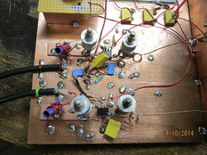
The convertors in more detail
If anybody want some more information, please send me a mail.
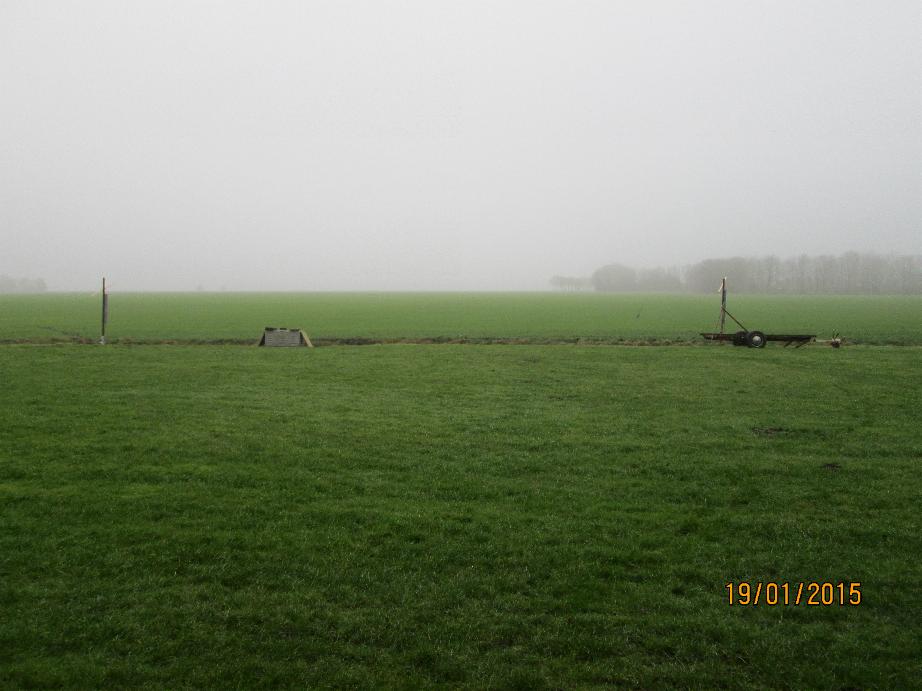
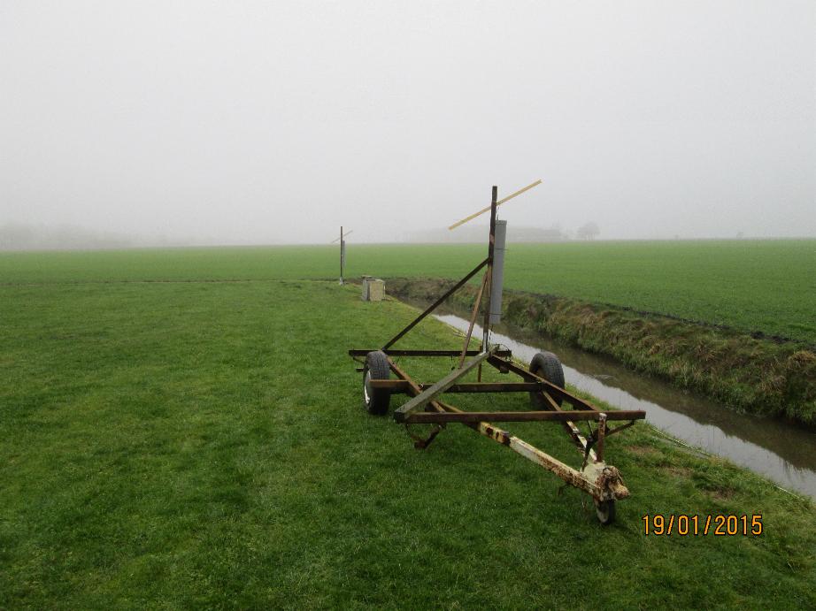
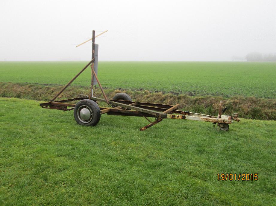
The 146 MHz radiotelescope in test phase
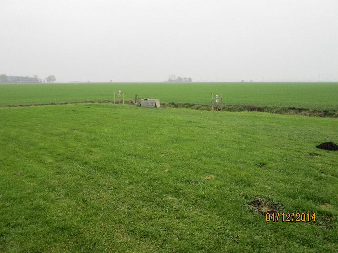
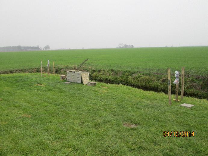
In some more detail
Left and Right are the two beam antennas
In the middel the fieldbox with a lot of electronics in it.
From this fieldbox go 2 coaxial cables of 80 meter length to the
caravan in which are the receivers and the computer
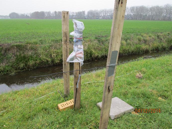
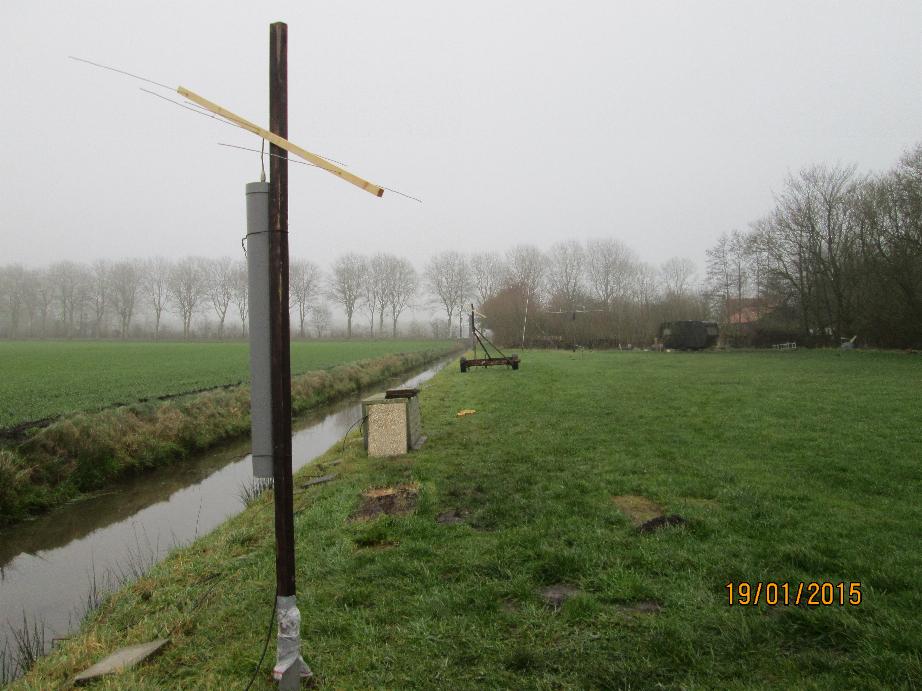
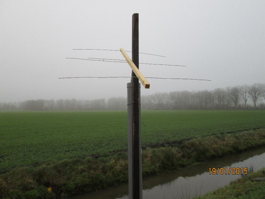
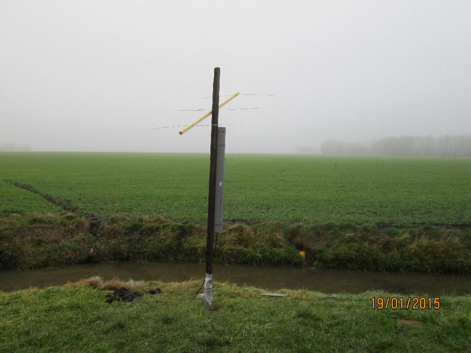
The frontend , the dipole antenna and a beam-reflector
Please don't laugh... it is working!
In the plastic is the antenna amplifier ( noise figure
is 0.2 db and amplification = 28 db) and a 10 db broadband
amplifier.